
Part Details | SHOULDERED SHAFT
3040-01-308-3519 A shaft having two or more different diameters (greater than 0.031 inches (0.79 millimeter)) along its length. It must have one or more of the following conditions: a specified surface finish designation in the range 1 to 125 microinches (0.025 to 3.2 micrometers) arithmetical average (AA), machined peripheral flat(s), circular groove(s), keyway(s), splines, threads, or holes. The ends and/or shoulders may be machined to accommodate bearings, couplings, and the like. It is not designed for use in aligning by fitting into corresponding holes of another item. For items used to support rotating members see AXLE(1), SHOULDERED. For items not having any of the above conditions see PIN, SHOULDER, HEADLESS. Excludes SHAFT(1), STRAIGHT; and AXLE(1), STRAIGHT.
Alternate Parts: 204654231, 204-65423-1, 3040-01-308-3519, 01-308-3519, 3040013083519, 013083519
| Supply Group (FSG) | NSN Assigned | NIIN | Item Name Code (INC) |
|---|---|---|---|
| 30 | SEP 27, 1989 | 01-308-3519 | 22914 ( SHAFT, SHOULDERED ) |
REFERENCE DRAWINGS & PICTURES
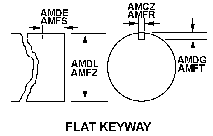
FLAT KEYWAY
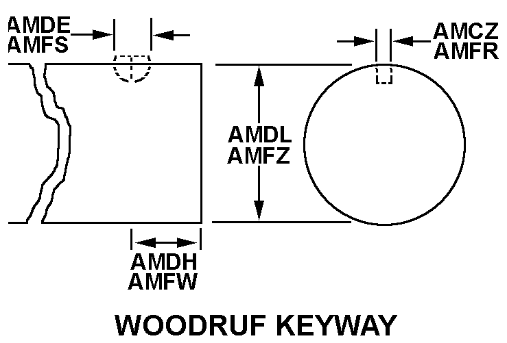
WOODRUFF KEYWAY
FLAT KEYWAY
WOODRUFF KEYWAY
Cross Reference | NSN 3040-01-308-3519
| Part Number | Cage Code | Manufacturer |
|---|---|---|
| 204-65423-1 | 81205 | THE BOEING COMPANYDBA BOEING |
Technical Data | NSN 3040-01-308-3519
| Characteristic | Specifications |
|---|---|
| FIRST END STYLE | 0 FLAT KEYWAY |
| MATERIAL | STEEL |
| FIRST END GROOVE WIDTH | 0.0100 INCHES NOMINAL |
| FIRST END DIAMETER | 0.5000 INCHES NOMINAL |
| END SIMILARITY | NOT IDENTICAL |
| SECOND END STYLE | 1 WOODRUFF KEYWAY |
| SECOND END KEYWAY WIDTH | 0.1520 INCHES MINIMUM AND 0.1540 INCHES MAXIMUM |
| SECOND END ANGLE BETWEEN KEYWAYS | 90.0 DEGREES NOMINAL |
| LARGEST STEP DIAMETER | 0.8736 INCHES MINIMUM AND 0.8746 INCHES MAXIMUM |
| OVERALL LENGTH | 13.500 INCHES NOMINAL |
| STEP QUANTITY | 3 |